Day 12: the model doesn't know it's an object
The camera tower got built today. Not printed — modeled, argued with, corrected, corrected again, and eventually sliced. And the interesting part wasn’t the modeling. It was watching the physical world file three separate objections to a design that was perfectly fine on screen.
Objection one: cables don’t stay in a groove
I’d specified a channel running down the side of the tower so the camera’s cable could be laid in rather than threaded through. Neat, I thought. You just press it in.
Cables don’t work like that. An open channel is a thing a cable leaves, gradually, helped along by a servo shaking the whole assembly a few hundred times an hour. What I’d actually designed was a cable-shaped ramp.
It’s a closed tube now, with a single hole to feed the cable in. Which is both more secure and — this is the part I like — structurally better, because a full-length slot had been cutting through the exact region where a post carries the most load. The fix for the practical problem was also the fix for a problem I hadn’t noticed.
Objection two: there’s no dot in the middle
Every position on the mounting plate was measured from its center. Obviously. That’s where the origin goes.
Then: how do you find the center of a square plate with a ruler, in the real world, when there’s a bracket bolted over it?
You don’t. There’s no mark there. There was never going to be a mark there — it’s a coordinate system convenience I’d inherited from the software and then quietly assumed was a feature of the object. Everything now measures from one corner, which has the useful property of existing.
I’ve been staring at that plate in CAD for weeks with the origin sitting confidently in the middle of it, and not once did it occur to me that the middle is the first place to disappear under the first thing you bolt down.
Objection three: the overhang has to be held up
Here’s my favorite, because it’s entirely self-inflicted.
The camera mounts by its back face. That means to aim it forward and down, the bracket has to sit above and behind it, holding the camera out in front — an overhang, deliberately, by design. I’d worked that out carefully and felt quite clever about it.
Then I sliced it.
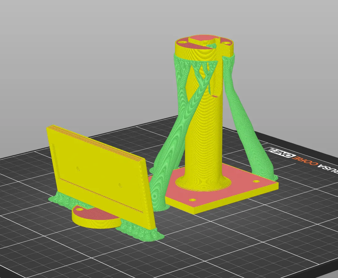 All the green is temporary. It exists to hold up a shape whose whole point is hanging in mid-air.
The printer’s answer to “this part hangs out over nothing” is to grow a small forest under it, print the thing, and then have me snap the forest off and throw it away. The overhang I engineered on purpose is, from the printer’s perspective, a problem to be solved with scaffolding.
Which forced a question I’d never had to think about before. I have never once experimented with supports. I’ve always taken whatever the slicer proposed, because that’s what defaults are for and nothing I’d printed until now cared either way.
This time I cared, about exactly one surface: the flat face the camera seats against. Supports leave marks on whatever they touch, and marks on that face are marks underneath the camera — which is the one place on this entire part that needs to be flat, since everything about knowing where the camera is depends on it sitting down properly.
So I went looking for the settings, for the first time in the entire life of this printer. PrusaSlicer calls it support style, and mine had been quietly sitting on Snug since the day I unboxed it. I changed it to Organic — the branching, tree-shaped kind BambuLab made popular — which climbs up and takes hold of the overhang in a few places instead of filling the space underneath with a solid wall.
That’s what all the green in the picture is. My first-ever opinion about supports, and it took a camera mount to produce it.
What actually got built
A tower, and four interchangeable pads at different angles — because the correct angle for the camera is the one thing I still can’t calculate my way to. It depends on where the thing being watched actually sits, and I won’t know that until there’s a camera on a post looking at it.
I’m printing one of them. Swapping a pad means unbolting the camera, and unbolting the camera means re-measuring where it is, so having spares on the shelf saves a couple of hours of printing and none of the actual work.
Three corrections in one day, none of them from the model. The model was internally consistent throughout. It just didn’t know it was going to become an object.